

Vacuum secondary function
- AirFuelSpark

- Oct 15, 2023
- 8 min read
Vacuum secondary talk!!!
(Disclaimer, yes, I wrote this in 15 minutes in a caffeinated frenzy, no I didn’t really proofread it all)
How many times has it been heard:
“Vacuum secondary Holleys are trash, you need a double pumper!”
Lets start this engineside chat by making a few things clear. I consider these to be truths, but like all truths, there is some grey area and some exceptions to the rule, so please, don’t give me one single and highly specific example why I’m wrong here. But by all means, feel free to add your info if you have some.
-There is zero reason a vacuum secondary carb should be slower than a double pumper. Is it possible? Yes, but it is not an inherent design issue.
-The main benefit to a mechanical secondary is in ease of tuning. Ie: you control all operations with your foot.
-The primary reason vacuum secondary carbs are considered slower is due to incorrect opening rates.
-If we are dealing with an original 1960s car, this entire debate is useless as double pumpers were not invented yet. The few instances mechanical secondaries were used were an incredibly small percentage. And we deal with factory original stuff here. If restoring your mustang to exact specs, a double pumper may be easier, but it is not an option.
Alrighty, secondary operation should be covered first.
Parts involved:
1. Secondary throttle shaft
2. Primary to secondary closing link
3. Vacuum housing and air routing
4. Diaphragm
5. Spring.
The secondary shaft. It has no direct solid connection to the primary. It is connected only to the diaphragm. Most of these throttle shafts have 4 teflon ribbons installed. These aid in both sealing from air leaks and having a super slick surface to work on.
Of note, Cobrajet and Boss carbs (and many others) do not have teflon ribbons.
Of note when working with older secondary shafts, many of them, especially the pre67 ones came with a brass throttle shaft. The main negative to this is they can be easily bent. Any sort of bend or bow can cause resistance and drag which will impact operation. Getting the throttle shaft as straight as possible is critical to function. Even drawing up the throttle plate screws too tightly can impact this.
On one end fixed is the channel for the closing link. On the other end attached with a screw is the diaphragm lever. This lever serves three functions.
First it is an attachment point for the diaphragm rod. Second it has a bent metal tab so the closed position is set. Third it has a metal tab to set the wide open throttle position.
Closing link serves a simple function. It only allows the secondary shaft to open if the primary is open. It also (hence the name) closes the secondaries when the primary throttle is closed.
Things worth mentioning:
-once the closing link is set, it should not require adjustment.
-It can be bent slightly to more fully close if desired.
-If too tightly closed, it can in fact partially hold open the primary.
-It should NOT be required for the secondaries to fully shut. The secondary throttle plates are sufficiently offset on the shaft that flowing air and diaphragm spring pressure should be able to hold the shaft in the fully closed position.
Vacuum housing and how air is routed.
I want you to envision a holley in front of you. Now imagine standing behind it and looking down from above. Primary throttle lever is on the left side, choke and secondary housing is on the right.
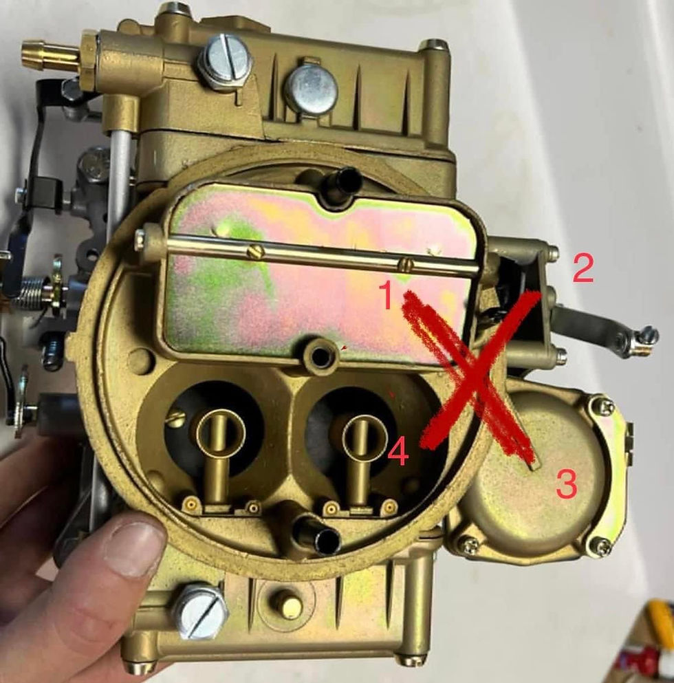
Ok. Now while looking down, Imagine a large X where the housing connects to the main body.
In the X we have numbers starting at the Upper left and going clockwise, 1, 2, 3, 4.
Number 1 is the signal hole. As the primary throttle is opened, two throttle plates begin to open and allow more air and fuel into the engine, incoming air rushes through the Venturi. Where our #1 is, there is a tiny hole, or piece of brass tubing in the right hand primary venturi.
As air flows past this hole it reduces pressure seen at this signal hole. As more air volume rushes past, the pressure becomes less and less. This pulls at the vacuum housing.
Number 2 in our X is where the chamber exits the chamber and meets the secondary housing. As it enters the housing, there were a few ways to tailor the air movement. Most commonly is a 3/16 stainless check ball with a seat. This slows opening and closing points as it takes time for the air to equalize on both sides of the ball. Later Ford and many others used a fixed oriface. On the 390GT and some Boss carbs this was a brass plug with a .040 drilled hole. I find that often the ball slows the opening too much. I can either drill for bypass air, or notch the seat that the ball sits in. This will make activity a but more rapid.
Same with the brass restriction. You can drill to size in order to allow more responsive action.
#4 is drilled on some carbs but not all. It is a bleed off hole, typically .040-.060 in size. The purpose of this is primarily to bleed off the draw seen at the vacuum housing. This can help tailor the opening point based on engine requirements. Why a bleed off?
Imagine using a large carburetor on a small engine. This engine would have a difficult time providing sufficient air volume to open the secondaries.
Take that exact same carb and put it on an engine with twice the displacement. The secondaries would flop open rapidly at even part throttle. Adding a bleed off can assist in this.
The vacuum housing diaphragm is the flexible seal that can turn the reduced pressure seen in the housing into mechanical motion. There are at least 4 different rod lengths available with the same diaphragm. Selection of length is fairly critical as some overly long rods will not allow the secondaries to open fully, whereas a too short one will not allow the secondary throttle to close completely.
The spring opposes this mechanical motion. There are a handful of different springs with differing wire gauges and lengths. These are classified by color. Not only do these allow different opening points, but they provide different opening rates.
Alright, function… lets imagine we can travel the path and experience how this works.
The primary throttle opens. As engine speed rapidly increases, a much larger volume of air is drawn into the engine. As this air passes our signal hole (1) in the venturi opposite the throttle lever a depression is seen at the hole. This depression is felt in the entire X that we mentioned earlier. Hole #4 provides a bleed off to balance the depression seen at #2.
As #2 is drawn on, that is seen in the vacuum housing. The stainless checkball or restriction inside the housing regulates the air leaving the topside of the diaphragm. As draw increases it overcomes the spring tension and draws the diaphragm up which lifts the rod and thus opens the secondary throttle.
Sounds complicated right? It really isn’t.
As primary throttle is closed, the depression inside the diaphragm housing lessens and everything reverses operation as the secondary shaft is closed.
Now that we understand the function and can see how each area can impact operation, we can finally begin to decide on the best way to make adjustments.
Adjustments to be made primarily consist of changing the spring.
I will reiterate that diaphragm rod length is insanely important. One of the reasons I began making Ford specific rebuild kits is because almost every generic kit be it from any of the manufacturers, including Holley, had the wrong length rod. It was very common to see a 715 or 735 carb which would only open the secondaries halfway.
About spring selection and tuning.
Colors for this range from white, short yellow, long yellow, plain, purple, black, etc.
If we use too weak of a spring, what happens?
Upon opening primary throttle, the secondaries flop open instantly.
Why is this bad?
When the primary throttle is opened, air initially speeds up into the engine, as the engine meets it’s load it slows until it can generate more power and speed up. At this moment when the air speeds up, if the secondaries start to open it can create a massive bog due to slowing air speed even less.
This reduced airspeed has a harder time lifting fuel from the bowls and dispersing it into the incoming airstream.
The engine would see a very lean spike and it would take the engine far longer to recover.
If the spring is slightly too strong, the primaries would open and the engine rpm would increase, more and more, etc without the secondaries opening. Power and acceleration is lost.
If the spring is waaay too strong (lookin at you Black spring), the secondaries would never open.
In an ideal world, throttle would open, engine rpm would increase. Engine speed would surpass cruising speeds, lets say 3000rpm and secondaries would begin to open slowly. The opening rate would match engine speed acceleration until max rpm is reached.
Variables in the how and why.
Engine size obviously plays a large roll in how fast the secondaries open, but lets assume you already have that handled with spring selection, etc.
why would I want to speed up or delay the opening rate?
The answer is load and usage.
Imagine a 2800lb race car with a high stall or manual transmission. Race tires, deep rear end gears, the works. Everything about this car is designed around fast acceleration. In this scenario, a rapid opening of the secondaries can be tolerated if not required. The engine can easily accelerate faster as it is seeing less of a load from the drivetrain and acceleration of the vehicle. A short lean spot is rapidly washed over as the engine itself can pull dramatically more air in less of a time. This engine with a full load going from 3,000 to 6,000rpm pretty rapidly.
Now on the other end of the spectrum, imagine a heavy truck towing a load. Sure on a flat road it is holding a steady throttle position, but now we are going up a steep incline. Engine speed slows as load increases, so we downshift to get higher rpms. In this case if the secondaries cracked open prematurely or rapidly, or possibly even at all, it may make for a huge loss of power at a very critical time.
If rpms and power requirements dictate secondary operation, it will need to be slow and steady increase as the air flow is not going to be increasing rapidly like our first example.
Ok dude, so I have my old truck with a 670 street revenger or whatever on it, what is the simplest way to tailor this opening rate?
If I had all the time to play with one vehicle, and I wanted to nail down this on it I would do it in one of these two ways:
-Get the modern adjustable secondary top. This way with a turn of a screw, you can change the rate of opening. Along the same lines, you can get a Holley quickchange top. This allows fast and easy spring changes.
To actually feel and experience this, we can assume you have the spring tuning kit with a handful of springs.
Pick the strongest one. lets say the black spring.
Go out with the car on the road and accelerate as quickly as possible. The secondaries will not open, this is fine. This rules out any bogs or lags in acceleration on the primary side.
Good. Now we know what it is like with just 2 venturi in action.
Now. Install the lightest spring. Typically a white or short yellow.
Do the same test. Feel the lag in acceleration? That is caused by the secondaries opening too rapidly.
Proceed to install heavier springs until the soft spot is eliminated. From this point further testing and tuning can be done to find the perfect spot.
-I’m a cheap guy. I would tap the secondary air entry on the housing where it meets X #2 and install a fixed restriction. An 8-32 or 10-32 set screw would allow enough space to drill the oriface from .040-.080
I would use a spring I know is too light and increase the oriface size until I got to where I was happy. If I accidentally overshot the size, easy enough to install a new set screw and drill undersized.
Testing procedure is pretty much the same as the above. The nice part about this setup is that with two replaceable tuning aids (spring and restriction) you can tailor opening point and speed far greater.
One additional way to increase draw on the secondary housing. You can install the small brass tube cut at a 45 in order to increase signal seen from the airflow.


Comments